Cassandra Logical Data Modeling
The task of a data modeler is to create order out of chaos without excessively distorting the truth. The finished product should be a data model that describes the structure, manipulation and integrity aspects of the data to be stored. To properly create a data model, the modeler will transform said chaos through three distinct stages. The first is a Conceptual Data Model, then a Logical Data Model, and lastly, a Physical Data Model. The first post on the Conceptual Data Model has been published. This post will cover the Logical data model. There will be a following post on the Physical data model. It will also walk through the creation of a full blown logical data model for a service scheduling application to be built with a Cassandra backend.
Logical Data Model
Logical data models build upon the Conceptual data model and takes into account the application’s workflow. This type of model builds upon what we know about the data so far and applies it to how our application will use the data. The product of the Logical data model is a mapping of Entity Relationship Diagrams to desired output of queries. This product will take the form of entities becoming tables, attributes becoming columns/fields, and relationships becoming keys.
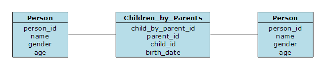
For example, let’s expand on the first example in the previous Conceptual Data Modeling post. We have established that a Person is an entity class and has potential relationships, such as genealogical or marriage. In the Logical Data Model, we would map the Person entity to a Person table. The attributes of name, gender, and age become columns/fields in the Person table. To map relationships, we would create a key columns/fields to use as reference points between tables.
Diagramming Logical Data Models
The idea of Logical data modeling has been around since the mid 1970s. At that time, a logical model, or schema, was one of two types, hierarchical or relational. It was meant to be completely independent of any technology platform. To diagram it, you would simply start by mapping objects/attributes/relationships over to tables with columns and keys.
The example above would look like the following diagram:
Once you’ve got the object entities mapped to tables, you may want to brush up on your rules of normalization. William Kent’s 1982 paper does a really good job of describing the first five degrees of normalization. Ideally, a logical data model is normalized to fourth normal form (4NF). If you’ve got a RDBMS background, then this is all making sense. If not, normalization is the process of organizing the columns and tables to minimize redundancy. There are 6 degrees of normalization. For logical schemas, we only need to go to the fourth. A table is in 4NF if and only if, every one of its non-trivial multivalued dependencies is either a candidate key or a superset thereof.
Logical Data Model for Cassandra
Now that I’ve explained to you what all that normalization stuff is intended for, set it aside. Cassandra is a different creature than traditional databases. It has more in common with a data warehouse, than a relational database. Cassandra thrives in a world where writing the same piece of data to multiple tables that are arranged with slightly different keys is the goal. Data redundancy is the norm and normalization is the enemy.
But why did we go over all that 4NF stuff? To be good at data modeling, you have to go through all of the steps to fully understand your data. Otherwise, you end up with anomalies that don’t fit and end up hurting the overall schema. There’s nothing worse that going to production with a design and realizing that you can’t build on it because you didn’t fully understand it’s needs in the first place.
Let’s see what a logical data model would look like for our Scheduling application that we first described in our earlier Conceptual data modeling post.
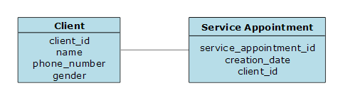
Client
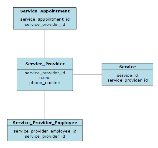
The Client entity has a 1:N (aka, one-to-many) relationship to the Service Appointment entity. This means that the Service Appointment entity will have a Client key to column (client_id).
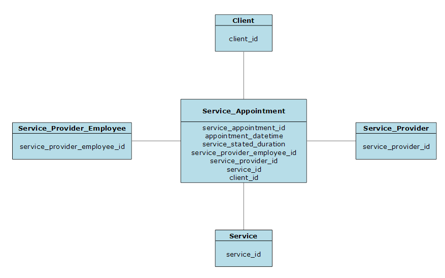
Service Appointment
The Service Appointment entity has a N:1 (aka, many-to-one) relationship to Client, Service Provider, Service, and Service Provider Employee. This means that the Service Appointment table will have key columns to those four entities (client_id, service_provider_id, service_id, service_provider_employee_id).
Service Provider
The Service Provider entity has a 1:N relationship to the Service Appointment, Service, and Service Provider Employee entities. This means that each of those three entities will contain a key column to the Service Provider entity (service_provider_id).
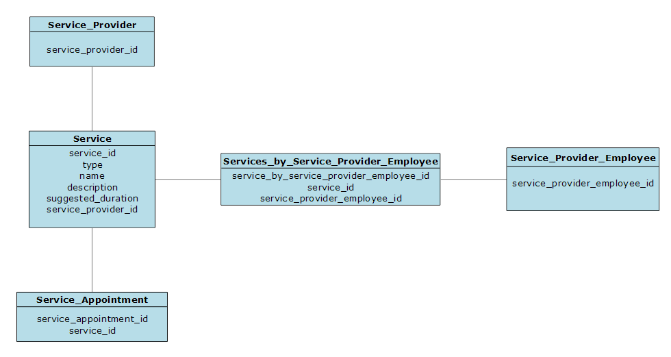
Services
The Services entity has a N:1 relationship to the Service Provider entity. This means that the Service entity will contain a key column to the Service Provider entity (service_provider_id). It also has a N:N (aka, many-to-many) relationship to the Service Provider Employee entity. This means that we will need a intermediate table to make this relationship possible. To accomplish this, we will create a new entity, Services by Service Provider Employee. This new entity will contain keys to both the Service and the Service Provider Employee entities (service_id and service_provider_employee_id). The Service entity also has a 1:N relationship to the Service Appointment entity. This means that the Service Appointment entity will contain a key to the Service entity (service_id).
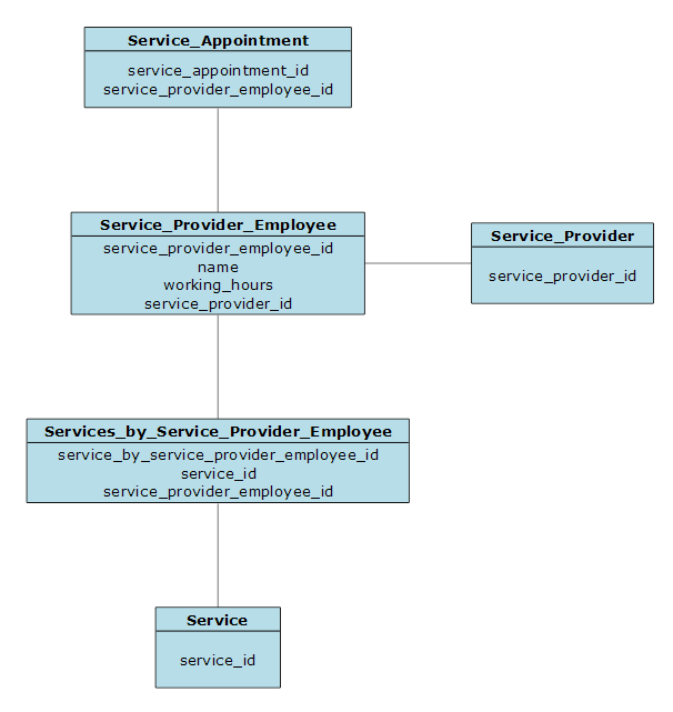
Service Provider Employees
The Service Provider Employee entity will have a 1:N relationship to Service Appointment. It will have a N:1 relationship to Service Provider. It will also have a N:N relationship to Service Provider Employee.
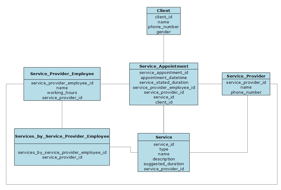
Final Logical Model
This combines everything we covered in the above models into a single logical model.
Query Driven Logical Data Model
Earlier, I mentioned that the product of the Logical data model is a mapping of Entity Relationship Diagrams to desired output of queries. Now that we know what all of our entities look like in table form, lets combine that with the queries that the application will be needing. This particular step is an addition to the classic data modeling approach. It is specific to Cassandra’s join-less nature. This will give us what the combined entities will look like as tables in a Cassandra environment.
Ideally, a designer will have gone through all the potential use cases and specified what the application flow will be. From those application flows, we can create queries that will satisfy those use cases.
The user/application flows below are just a small number that could be present in a full-blown application.
-
Search for a client by name.
-
Search for a client by phone number.
-
Get all scheduled service appointment by client for date range.
-
Get all scheduled service appointment by employee for date range.
Cassandra Queries
Early on in my Cassandra career, I was told that the best way to model your Cassandra data is to map a single query to a table. So for every data results piece of the application, it is only asking a single Cassandra table to retrieve the needed data. With this in mine, we need to start by defining the filter criteria for each query. The next four sections will illustrate the above use cases and how you can create Cassandra tables that show very similar data but are searched differently.
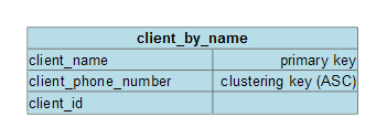
Client by Name
This result set of data will return all of the clients that have a given name. We will want the name to be the primary key and then list all clients by the next most identifying piece of data, phone number.
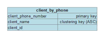
Client by Phone Number
This result set of data will return all of the clients that have a given phone number. We will want the phone number to be the primary key and then list all the clients’ names.
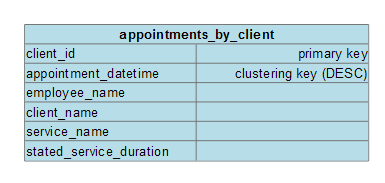
Service Appointment by Client
This query will return all of the service appointments that a given client has scheduled. We will want to search by client_id and then list all of the appointments in chronological order.
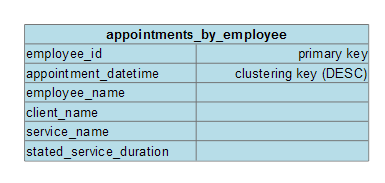
Service Appointment by Employee
This query will return all of the service appointments that a given employee has scheduled. We will want to search by employee_id and then list all of the appointments in chronological order.
Summary
At this point in this data modeling series, you should have a good understanding of what Conceptual & Logical Data Models are. So far, I’ve shown you how to describe your data as entities and to map those entities to tables and then to Cassandra queries. The next post will continue the series and dive into the Physical Data Model.